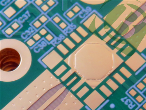
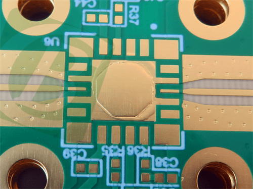
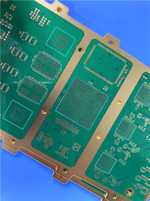
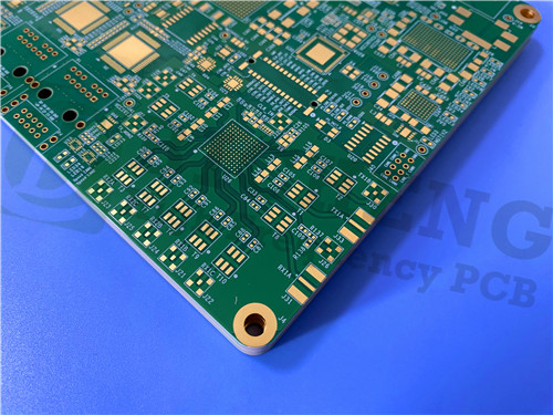
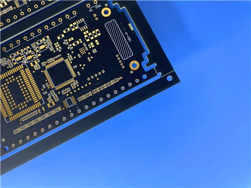
14-Layer Megtron-6 ENEPIG PCB – High Speed Low Loss Multilayer Board
1. Introduction to Megtron-6 PCB
The MEGTRON 6 Family, including MEGTRON 6(G), MEGTRON 6(K), MEGTRON 6(N), are the original PCB industry standards. The products are ideal for mobile, networking, and wireless applications requiring high-speed, ultra-low loss circuit materials. MEGTRON 6 provides excellent high-density interconnect (HDI) and thermal performance.
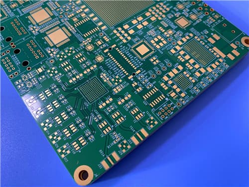
Megtron-6 laminates feature low dielectric constant (Dk) glass cloth and ultra-low loss characteristics, making them perfect for high-speed digital and RF applications. This 14-layer rigid PCB is constructed with R-5775 laminate and R-5670 prepreg, offering exceptional signal integrity and thermal reliability.
2. Key Features of Megtron-6 PCB
Ultra-low loss, highly heat resistant circuit board material Low Dielectric Constant (Dk) Glass Cloth – Laminate R-5775 / Prepreg R-5670 Dielectric Constant (Dk): 3.4 @ 1GHz / 3.4 @ 12GHz Dissipation Factor (Df): 0.002 @ 1GHz / 0.004 @ 12GHz Glass Transition Temperature (Tg): 185°C (DSC) / 210°C (DMA) Thermal Decomposition (Td): 410°C CTE (X/Y): 14-16 ppm/°C; CTE (Z): 45 ppm/°C (α1), 260 ppm/°C (α2) Thermal Conductivity: 0.42 W/m·K Volume Resistivity: 1×10⁹ MΩ·cm; Surface Resistivity: 1×10⁸ MΩ Water Absorption: 0.14% Flammability: 94V-0 Resin Plugged Vias (IPC-4761 TYPE VII)
3. Benefits of Megtron-6 PCB
Ultra-low loss enables high-speed signal transmission with minimal attenuation Low Dk and Df ensure excellent high-frequency performance up to 58GHz High Tg (185°C) and Td (410°C) provide outstanding thermal reliability Low CTE matched to copper for excellent plated through-hole reliability Resin plugged vias (IPC-4761 TYPE VII) enhance reliability and prevent solder wicking ENEPIG finish offers excellent solderability and wire bondability Ideal for HDI designs with fine lines and spaces Excellent dimensional stability and low warpage
4. PCB Construction Details
| Item | Specification |
|---|
| Base material | Megtron-6 (R-5775 Laminate / R-5670 Prepreg) |
| Layer count | 14-layer rigid |
| Board dimensions | 178.8mm x 169mm = 4PCS (2×2 array), ±0.15mm |
| Edge rails | 5mm on each side (panelization) |
| Minimum Trace/Space | 4/4 mils |
| Minimum Hole Size | 0.2mm |
| Blind vias | No |
| Finished board thickness | 1.64mm |
| Finished Cu weight | Inner: 0.5 oz (18μm) / Outer: 1 oz (35μm) |
| Via plating thickness | 20 μm |
| Surface finish | ENEPIG (Nickel-Palladium-Gold) |
| Top Silkscreen | White |
| Bottom Silkscreen | White |
| Top Solder Mask | Green |
| Bottom Solder Mask | Green |
| Resin Plugged Vias | IPC-4761 TYPE VII |
| Quality standard | IPC-3 |
| 100% Electrical test | Used prior to shipment |
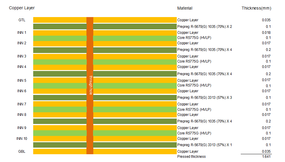
5. PCB Stackup (14-Layer Rigid Structure)
Layer 1 (Top) – Copper 35 μm (1 oz)
Prepreg R-5670 – Dielectric
Layer 2 – Copper 18 μm (0.5 oz)
Core R-5775 – Dielectric
Layer 3 – Copper 18 μm (0.5 oz)
Prepreg R-5670 – Dielectric
Layer 4 – Copper 18 μm (0.5 oz)
Core R-5775 – Dielectric
Layer 5 – Copper 18 μm (0.5 oz)
Prepreg R-5670 – Dielectric
Layer 6 – Copper 18 μm (0.5 oz)
Core R-5775 – Dielectric
Layer 7 – Copper 18 μm (0.5 oz)
Prepreg R-5670 – Dielectric
Layer 8 – Copper 18 μm (0.5 oz)
Core R-5775 – Dielectric
Layer 9 – Copper 18 μm (0.5 oz)
Prepreg R-5670 – Dielectric
Layer 10 – Copper 18 μm (0.5 oz)
Core R-5775 – Dielectric
Layer 11 – Copper 18 μm (0.5 oz)
Prepreg R-5670 – Dielectric
Layer 12 – Copper 18 μm (0.5 oz)
Core R-5775 – Dielectric
Layer 13 – Copper 18 μm (0.5 oz)
Prepreg R-5670 – Dielectric
Layer 14 (Bottom) – Copper 35 μm (1 oz)
Total thickness: 1.64mm (including copper layers)
6. PCB Statistics
Components: 42
Total Pads: 186
Thru Hole Pads: 94
Top SMT Pads: 92
Bottom SMT Pads: 0
Vias: 128
Nets: 4
7. Megtron-6 Material – Product Introduction
Ultra-low Loss, Highly Heat Resistant Circuit Board Materials. Low Dielectric Constant (Dk) Glass Cloth – Laminate R-5775 / Prepreg R-5670. The MEGTRON 6 Family, including MEGTRON 6(G), MEGTRON 6(K), MEGTRON 6(N), are the original PCB industry standards. The products are ideal for mobile, networking, and wireless applications requiring high-speed, ultra-low loss circuit materials. MEGTRON 6 provides excellent high-density interconnect (HDI) and thermal performance.
.jpg)
8. Features and Benefits Summary
| Feature | Benefit |
|---|
| Dk 3.4 @ 1GHz / 12GHz | Stable dielectric constant for consistent impedance control |
| Df 0.002 @ 1GHz / 0.004 @ 12GHz | Ultra-low loss for high-speed signal integrity |
| Tg 185°C (DSC) / 210°C (DMA) | Excellent thermal stability for lead-free assembly |
| Td 410°C | High thermal decomposition resistance |
| CTE matched to copper (14-16 ppm/°C) | High reliability plated through holes |
| Resin Plugged Vias (IPC-4761 TYPE VII) | Enhanced reliability and prevention of solder wicking |
| ENEPIG finish | Excellent solderability, wire bondability, and corrosion resistance |
| IPC-3 standard | High quality and reliability for demanding applications |
9. Megtron-6 (R-5775/R-5670) Typical Properties
| Property | Typical Value | Units | Condition | Test Method |
|---|
| Tg (DSC) | 185 | °C | As received | DSC |
| Tg (DMA) | 210 | °C | As received | DMA |
| Td (Thermal Decomposition) | 410 | °C | As received | TGA |
| T288 (Without Cu) | >120 | min | As received | IPC-TM-650 2.4.24.1 |
| T288 (With Cu) | >120 | min | As received | IPC-TM-650 2.4.24.1 |
| CTE (X-axis) | 14-16 | ppm/°C | <Tg | IPC-TM-650 2.4.24 |
| CTE (Y-axis) | 14-16 | ppm/°C | <Tg | IPC-TM-650 2.4.24 |
| CTE (Z-axis α1) | 45 | ppm/°C | <Tg | IPC-TM-650 2.4.24 |
| CTE (Z-axis α2) | 260 | ppm/°C | >Tg | IPC-TM-650 2.4.24 |
| Thermal Conductivity | 0.42 | W/m·K | — | — |
| Volume Resistivity | 1×10⁹ | MΩ·cm | C-96/35/90 | IPC-TM-650 2.5.17.1 |
| Surface Resistivity | 1×10⁸ | MΩ | C-96/35/90 | IPC-TM-650 2.5.17.1 |
| Dk @ 1GHz | 3.4 | — | C-24/23/50 | IPC-TM-650 2.5.5.9 |
| Dk @ 12GHz | 3.4 | — | C-24/23/50 | Balanced-type Circular Disk Resonator |
| Df @ 1GHz | 0.002 | — | C-24/23/50 | IPC-TM-650 2.5.5.9 |
| Df @ 12GHz | 0.004 | — | C-24/23/50 | Balanced-type Circular Disk Resonator |
| Water Absorption | 0.14 | % | D-24/23 | IPC-TM-650 2.6.2.1 |
| Poisson's Ratio | 0.2 | — | — | — |
| Flexural Modulus (MD) | 19 | GPa | — | — |
| Flexural Modulus (TD) | 18 | GPa | — | — |
| Peel Strength (1 oz Cu, H-VLP) | 0.8 | kN/m | As received | IPC-TM-650 2.4.8 |
| Flammability | 94V-0 | — | C-48/23/50 | UL |
10. Impedance Control Specifications
| Structure | Target Impedance | Width | Spacing |
|---|
| Microstrip | 50Ω | 0.2mm | — |
| Microstrip | 100Ω | 0.1mm | 0.101mm |
| Stripline | 50Ω | 0.1mm | — |
| Stripline | 100Ω | 0.2mm | 0.102mm |
11. Primary Application Areas
High-speed networking equipment (routers, switches, servers) Wireless infrastructure (5G base stations, antennas) Mobile devices and handheld electronics High-density interconnect (HDI) designs Test and measurement equipment Automotive radar and advanced driver assistance systems (ADAS) Data center and cloud computing hardware
12. Quality Assurance
Type of artwork supplied: Gerber RS-274-X Accepted standard: IPC-3 Availability: Worldwide 100% Electrical test prior to shipment Resin Plugged Vias per IPC-4761 TYPE VII
|